
IEC 60118-4 Has Changed:Part 1 Maximum Power Bandwidth
Why is full p![]() ower bandwidth to 5kHz not necessary?
ower bandwidth to 5kHz not necessary?
Normal hearing (and hearing aids) is less sensitive to low frequencies.
This means for the perception of equivalent loudness, we need less power at high frequencies compared to what is required at low frequencies.
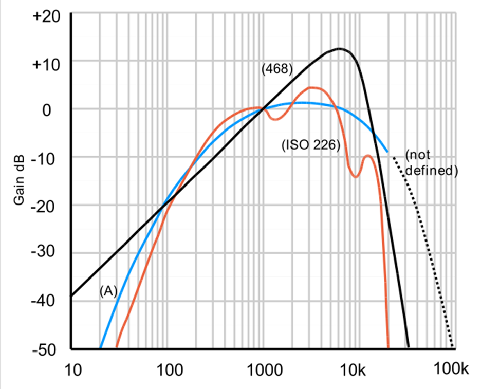
The blue curve on the graph above is described as A weighted and is an approximation to the sensitivity of normal hearing . The curve below shows the sensitivity of a typical hearing aid.
Both graphs show a similar response.
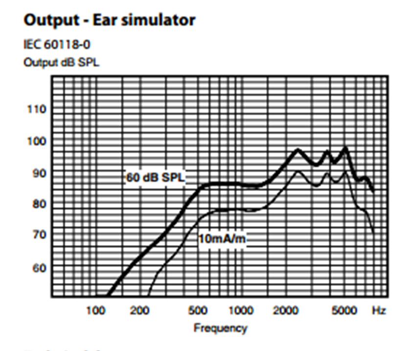
ITU speech shown below and other test signals used to simulate speech are opposite in characteristic to the response curves shown above. More power is required at the lower frequencies
At 5kHz the signal level is approx. 24dB down on that at 1 kHz. For every 6dB reduction in field strength the loop current is halved. This implies that at 5kHz , a 1/16th of the current is required compared to that at 1kHz which is (1/16)2 of the power ( P=I2R) so the system does not need to be capable of delivering full power all the way to 5kHz
Why do we measure at 5kHz if the Maximum power bandwidth is 1.6kHz
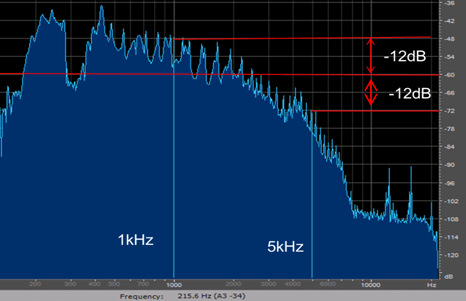
When commissioning hearing loop systems in accordance with the IEC standard, we check the magnetic field strength at 5kHz (and 100Hz) to ensure it is no lower than what we have measured at 1kHz. This test is only to determine whether the constructional metal is absorbing the higher frequencies. It is conducted with the output of the amplifier turned down; -12dB in the case of Univox, other manufacturers choose to use less demanding test signals such as pink noise.
With the output set to deliver -12dB (small signal) and assuming the loop design is within our guidelines, the amplifier will be delivering a constant current over the full frequency range. **So if the field strength is not the same at 5kHz as measured at 1kHz the difference is due to magnetic absorption. We can compensate for this by using narrow loops or by using metal loss compensation control.
![]() The FSM 2.0 Field Strength Meter
The FSM 2.0 Field Strength Meter
The FSM 2.0 is a microprocessor controlled instrument using multi-tone signals to make advanced measurements of induction loop systems quick, accurate and easy. It is the only FSM to fully satisfy the demands of the IEC60118-4 standard by being capable of measuring noise levels down to -47dB. And since it is  programmable, its mode of operation can be updated to reflect changes to the standard as they occur. The instrument has a clear, backlit, LCD display and steps through the required measurements in a logical sequence, matching the test certificate to simplify the certification process. With sharp, narrow band filtering and a noise spectrum display function, spill control and background noise assessments are also made easy.
With the dedicated 1.6kHz test tone available for this meter, the maximum power bandwidth is easy to assess
The 2015 edition of the IEC standard, IEC 60118-4:2015 includes an additional performance test, Amplifier Overload at 1.6kHz (Maximum Power Bandwidth)
The test should be carried out on the induction loop system during the commissioning process. It is aimed at checking that the amplifier is capable of delivering *full current into the load presented by the loop up to 1.6kHz.
If the amplifier is not capable of maintaining this output current, there is a possibility that voltage clipping will occur on some signal peaks which may cause audible signal distortion. (As loop systems rely on the loop current and not voltage a small amount of voltage clipping is not an issue and will not affect the perceived audio quality even though it is visible on an oscilloscope or a clip detector. So any tests on the maximum power bandwidth should be done in conjunction with a listening test.
![]() *full current in the context of this article is the rms current at which the field strength of 0dB ±3dB is achieved using a 1kHz sine wave tone or equivalent and where metal loss correction is correctly adjusted.
*full current in the context of this article is the rms current at which the field strength of 0dB ±3dB is achieved using a 1kHz sine wave tone or equivalent and where metal loss correction is correctly adjusted.
** The loop cable is inductive It has both a d.c and an a.c resistance (reactance). The a.c component is frequency dependent . The higher the frequency, the higher the reactance and therefore the higher the voltage output from the amplifier required to maintain a constant current.
![]() The Univox design software defaults to designing for Speech, 1.6kHz. So providing you follow the design and use the cable type and length specified, including feed cables, your system should automatically meet this new requirement (assuming you set the same levels as you chose in the software and all other assumptions are correct)
The Univox design software defaults to designing for Speech, 1.6kHz. So providing you follow the design and use the cable type and length specified, including feed cables, your system should automatically meet this new requirement (assuming you set the same levels as you chose in the software and all other assumptions are correct)
Testing for maximum power bandwidth to 1.6kHz
There are several methods that can be used to check the maximum power bandwidth of the system. The most accurate requires the use of an oscilloscope . This method is not covered in this document as we do not expect many installers will have access to an oscilloscope in the field.
1.) For loop amplifiers with a ‘peak voltage clip’ LED
The most recent models in the Univox range include a ‘peak voltage clip ’LED.
Method A
With the system setup to deliver the ***correct field strength (0dB±3dB) using a 1kHz tone or equivalent apply the live signal to the system and monitor the LED. It should remain off although the occasional flicker on the peaks of the signal are acceptable.
listening test is required to complete the assessment.
This is probably the least stringent of acceptable test methods. Although the input signal is not analysed and there is no confirmation that the live signal includes full power frequency components >=1.6kHz. Either the system passes because it has adequate power bandwidth or based on actual inputs, the system does not need it.
Method B
Using a 1kHz sine wave tone or equivalent set the system up to deliver the ***correct field strength (0dB ±3dB). Now apply a 1.6kHz sine wave tone. If the ‘Voltage clip’ LED remains off, the maximum power bandwidth is=> 1.6kHz.
A listening test is required to complete the assessment.
2.) For loop amplifiers without a ‘peak voltage clip’ LED
Using a 1kHz sine wave tone or equivalent set the system up to deliver the ***correct field strength (0dB ±3dB). Now apply a 1.6kHz sine wave tone and measure the field strength. It should not have changed. Any drop in field strength indicates that the amplifier is voltage clipping and is not able to deliver the required current at this frequency.
('Squaring' of the current waveform as observed on an Oscilloscope is a more precise method)
A listening test is required to complete the assessment
![]()
***The standard does allow the field strength at 1kHz to be reduced by 1dB before applying the 1.6kHz tone, but metal loss compensation must be applied
The Univox Log Book and Commissioning Certificate now include the 1.6kHz Maximum Power Bandwidth Check.
Both documents are available as PDF Forms and can be downloaded from the knowledge centre on our website.
http://www.univoxaudio.co.uk/log-book
To access you will need to create an account and log in


